15 October 2026
OPGW Cables
OPGW Cables: Specifications, Hardware Fittings and Installation
OPGW combines earthing and fibre optic communication in a single conductor strung at the earthwire position on a transmission tower. It replaces a conventional galvanised steel earthwire without adding a separate cable run, giving the utility a communication path along the same route as the power line.
What OPGW Does on a Transmission Line
A transmission tower carries phase conductors and, above them, one or more earthwires. The earthwire’s function is to intercept lightning strikes and provide a path to ground, protecting the phase conductors below. OPGW performs this same earthing function while carrying optical fibres in its core, so the utility gets a dedicated communication link for protection signalling, SCADA and telecom traffic without stringing an additional cable.
This dual function is the reason OPGW is specified on new transmission lines and increasingly retrofitted onto existing ones during earthwire replacement.
Construction
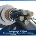
An OPGW cable is built in layers around a central fibre unit.
Fibre Core
The optical fibres sit inside a loose tube or a stainless steel tube at the centre of the cable, isolated from the outer mechanical layers so that fault current and mechanical stress do not reach the fibres. Fibre count is specified according to the utility’s current and anticipated communication requirement, and typically ranges from single digits for a basic protection link to higher counts where leased telecom capacity or future expansion is planned.
Metallic Layers
Outside the fibre unit, OPGW uses one or more layers of aluminium clad steel wires, aluminium alloy wires, or a combination of the two. Aluminium clad steel gives the cable most of its short circuit current capacity and tensile strength, while the aluminium cladding provides corrosion resistance and conductivity. The specific layer combination and wire diameter are selected to meet the short circuit current and mechanical load requirement of the route.
Central Tube Material
The tube housing the fibres is either stainless steel or aluminium, depending on the level of mechanical and thermal protection required. Stainless steel tube construction is generally specified where higher short circuit withstand is needed at the core, while aluminium tube construction is used where the outer metallic layers alone meet the short circuit requirement.
How to Read an OPGW Cable Specification
An OPGW cable specification sheet describes several parameters together, and a specification is only meaningful when these are read as a set rather than individually.
Short Circuit Current Capacity
This defines the current the cable can carry during a fault without exceeding the temperature limit of the fibres or the metallic layers. It is expressed for a defined fault duration, commonly one second. A cable sized for a lower short circuit current on a route with higher fault levels will fail under fault conditions even if every other parameter is adequate.
Tensile Strength
Rated tensile strength (RTS) determines the mechanical load the cable can withstand during stringing and under working tension, including wind and ice loading where applicable. This value, combined with span length and tower spacing, determines the sag and tension calculation for the line.
DC Resistance
DC resistance per kilometre affects both the earthing performance and the current-carrying behaviour of the cable during a fault. Lower resistance improves fault current dissipation but is a function of the metallic layer composition rather than an independent design choice.
Sag and Tension
Sag and tension figures are calculated for the specific span, conductor configuration and climatic conditions of the line, using the cable’s stress-strain characteristics. A specification without a sag and tension chart appropriate to the actual route conditions is incomplete for construction purposes.
[CONFIRM: figure needed] where a specific numeric range for any of these parameters is required for a named Advait product line, since exact values depend on the fibre count, layer construction and route conditions of each project and should not be generalised into a single figure.
OPGW Hardware Fittings
OPGW cable requires a matching set of hardware fittings, each suited to its position on the tower and its mechanical function.
| Fitting |
Function |
Typical Position on Tower |
| Suspension clamp |
Supports the cable at intermediate towers without gripping it rigidly, allowing minor movement |
Straight-line, intermediate towers |
| Tension clamp |
Anchors the cable at dead-end and angle towers, holding full working tension |
Dead-end and angle towers |
| Vibration damper |
Reduces wind-induced vibration (aeolian vibration) that causes fatigue over the cable’s service life |
Near suspension and tension points, spaced per span length |
| Downlead clamp |
Guides the cable from the tower peak down to the joint box or termination point |
Tower body, below the earthwire peak |
| Joint box |
Houses fibre splices and protects them from moisture and mechanical damage |
Tower body, typically at a height accessible for maintenance |
Earth Wire Suspension Clamp
The earth wire suspension clamp is the specific suspension fitting used at the earthwire position, distinct from conductor suspension clamps in its clamping force and body design, since it must maintain electrical continuity for earthing while supporting the OPGW cable without damaging the fibres inside. Selecting a conductor-rated suspension clamp for this position is a common error and can crush the cable’s outer layers under working tension.
Installation Sequence and Why OPGW Stringing Differs From Conductor Stringing
Stringing OPGW follows the same general pulling and tensioning method used for conductors, but with additional precautions specific to the fibre core.
Sequence Overview
- Pilot wire installation and running block setup at each tower
- Payout of OPGW from the drum, using a bull wheel tensioner set to a controlled tension throughout
- Sagging to the calculated tension for the span and temperature at the time of stringing
- Clamping at suspension and tension points using the correct fitting for each position
- Splicing at joint box locations, followed by fibre testing before the line is commissioned
Key Differences From Conductor Stringing
OPGW cannot be pulled through running blocks under uncontrolled tension or allowed to twist, since excessive tension or torsion can damage the internal fibres without any visible external sign. Bending radius during stringing and at the joint box must stay within the manufacturer’s specified minimum, and the cable requires fibre continuity testing before and after stringing to confirm no damage occurred during installation. Conductor stringing has no equivalent requirement, since a conductor’s electrical performance is not affected by bend radius or torsion in the same way.
Splice Enclosures and Joint Box Placement
Joint boxes house the splice points where individual fibre lengths are joined, either at manufacturing-length intervals or wherever a branch connection to a substation or telecom point is required. Joint boxes are typically mounted on the tower body at a height that allows maintenance access without requiring a full climb to the peak, and their position is planned during design so that splice loss and cable routing are both accounted for before construction begins.
Common Specification Mistakes in Tenders
A tender specification that lists short circuit current, tensile strength and fibre count without specifying the fault duration for the short circuit rating leaves the figure open to interpretation, since the same cable performs differently against a 0.2 second fault rating and a 1 second rating. Specifications that omit the sag and tension chart for the actual span and climatic condition of the route require the manufacturer to assume conditions, which can result in a cable that is mechanically unsuited to the line once installed. Fitting schedules that specify the cable but not the matching suspension and tension clamp ratings are a similarly common gap, since a mismatched clamp can compromise the installation regardless of cable quality.
Conclusion
OPGW specification and installation depend on reading short circuit current, tensile strength, DC resistance and sag and tension together, against the actual conditions of the route, rather than as a generic data sheet. Fitting selection, particularly at the earth wire suspension clamp position, and a stringing sequence that accounts for the fibre core’s sensitivity to tension and torsion, determine whether the installation performs as specified over the line’s service life. For OPGW cable and fitting specifications, see Advait’s OPGW cable range.